
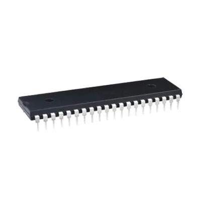

DIP ICL7107CPL, For Electronics
ICL7107 Pinout Configuration
Pin Number
Pin Name
Description
1
Supply voltage (+)
Provides the operating voltage for the IC
2,3,4,5,6,7 and 8
7-Segment 4th digit
These pins are connected to the 7-segment display for displaying the once digit of output value.
9,10,11,12,13,14 and 25
7-segment 3rd digit
These pins are connected to 7-segment for displaying the tenth digit
15,16,17,18,22,23 and 24
7-sement 2nd digit
These pins are connected to 7-segment for displaying the hundredth digit
19 and 20
7-segment 1st digit
These pins are connected to 7-segment for displaying the thousandth digit
21
Ground
Connected to the round of the system
26
Supply voltage (-)
Provide the negative supply voltage
27
Signal integrate
Connected to a capacitor
28 and 29
Auto Zero and buff
Connected to capacitor and resistor network
30 and 31
Input High and Input Low
The analog voltage that has to be measured is connected here
32
Common
Connected to ground
33 and 34
Cref+ and Cref-
Capacitor is connected across these pins for neutralizing fluctuations in reference voltage
35 and 36
Reference High and Reference Low
Either can supply reference voltage or use internal reference voltage
37
Test pin
Not used during operation
38, 39 and 40
OSC1, OSC2, OSC3
Use RC network top set oscillator frequency
Features
3 ½ bit (0-1999) ADC module with 4-digit 7-segemnt display driver
Supply Voltage: Single Supply 0-6V
Dual Supply -15 to +15V
3 ½ ADC module
Analog input voltage is equal to supply voltage
Internal Oscillator is available
Typical operating frequency : 48kHz
Digital output value : 0 – 1999
Can drive four 7-segment display
Available in 40-pin PDIP, and MQFP
Note: Complete technical information can be found in the ICL7107 Datasheet linked at the bottom of this page.


Reviews
There are no reviews yet.