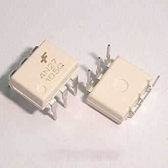
The 4N28 is an Industry Standard Single Channel Phototransistor Coupler. This family includes the 4N25, 4N26, 4N27 and 4N28. Each OPTOCOUPLER consists of gallium arsenide infrared LED and a silicon NPN phototransistor. In the chip the primary circuit and secondary circuit are isolated electrically. The pair of diode and phototransistor is there to provide optical trigger mechanism between the primary and secondary circuit.
4N28 Pinout Configuration
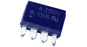
4N28 is a six pin IC which is available in various packages. Basically we use only four pins in the chip but can use up to five pins. The internal connections of diode and photo transistor are described below.
Pin Number
Pin Name
Description
1
Anode (A)
Positive terminal of internal IR LED
2
Cathode (C)
Negative terminal of internal IR LED
3
NC
No Connection
4
Emitter (E)
Emitter of internal
PHOTO TRANSISTOR
5
Collector (C)
Collector of internal
PHOTO TRANSISTOR
6
Base (B)
Base of internal
PHOTO TRANSISTOR
4N28 Features and Specifications
Interfaces with common logic families
Isolation test voltage 5000VRMS
Input-Output coupling capacitance < 0.5pF
Input-Output isolation voltage: 500VRMS
IR LED Forward Voltage for turning ON: 1.2V-1.5V (Typically 1.3V, 1.5V being absolute maximum forward voltage)
IR LED Forward Current during ON (IF): 10mA - 80mA (Typically 10mA, 80mA being absolute maximum forward current)
IR LED MaximumReverse Voltage: 6V
IR LED Maximum Reverse Current: 10uA
Maximum voltage across COLLECTOR and EMITTER of PHOTO TRANSISTOR: 70V
Maximum current allowed trough TRANSISTOR COLLECTOR(IC): 100mA
Current Transfer Ration (CTR): 10%
Typical Rise Time: 3us
Typical Fall Time: 3us
No additional power needed to be applied for chip for making it work.


Reviews
There are no reviews yet.