
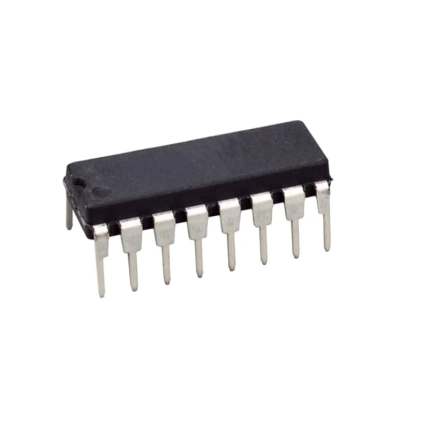
CD4026 7 Segment Counter
CD4026 7 Segment Counter is a 4000 series IC. This is a CMOS seven-segment counter IC and can operate at very low power. Its a decade counter, counts in decimal digits (0-9). It is use to display numbers on seven segment displays and it increments the number by one when a clock pulse applies to its PIN 1
Means more the clock pulse rate, faster the numbers change in 7 Segment Display. Below is the pin diagram and pin description of 4026 IC:
CD4026 7 Segment Counter Pin Configuration:
Number Name Description
1 Clock (CLK) The counting happens when this clock pulse goes high, this pin is normally connected to 555 timer or other uC to produce a pulse
2 Clock Inhibit (INH) Connected to the Ground (low) of the circuit, to enable clock pin
3 Enable Input (DEI) This pin is connected to +5V (high) to enable the output pins (Out A to Out G)
4 Enable Output (DEO) This is an output which always stays high, this pin will be only if more than one CD4026 IC is used (cascaded)
5 Divide by 10 (CO) This is the carryover output pin; it produces a pulse after counting till 9. This pin will be only if more than one CD4026 IC is used (cascaded)
6,7,9,10,11,12,13 Out A,B,C,D,E, F,G These are the decoded output pins which must connect to 7-Segment display.
8 Ground The ground pin must connect to the ground of the circuit
14 Not 2 out (UCS) This is Ungated C segment pin. This is an output pin which will rarely use when division is require.
15 Reset This input pin when make high (+5V) will reset the count to 0.
16 VCC This pin powers the IC, typically +5V is use.


Reviews
There are no reviews yet.