



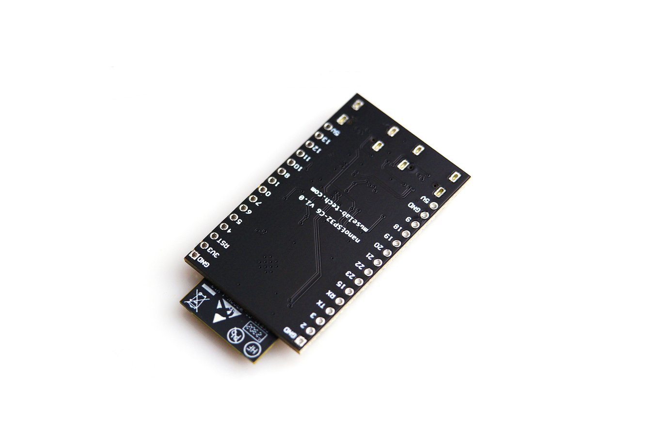




ESP32-C6 Development Board
| SP32-C6-WROOM-1 or ESP32-C6-WROOM-1U | ESP32-C6-WROOM-1 and ESP32-C6-WROOM-1U are general-purpose modules supporting Wi-Fi 6 in 2.4 GHz band, Bluetooth 5, and IEEE 802.15.4 (Zigbee 3.0 and Thread 1.3). They are built around the ESP32-C6 chip, and comes with a 8 MB SPI flash. ESP32-C6-WROOM-1 uses on-board PCB antenna, whereas ESP32-C6-WROOM-1U uses external antenna connector. For more information, see |
| Pin Header | All available GPIO pins (except for the SPI bus for flash) are broken out to the pin headers on the board. |
| 5 V to 3.3 V LDO | Power regulator that converts a 5 V supply into a 3.3 V output. |
| 3.3 V Power On LED | Turns on when the USB power is connected to the board. |
| USB-to-UART Bridge | Single USB-to-UART bridge chip provides transfer rates up to 3 Mbps. |
| ESP32-C6 USB Type-C Port | The USB Type-C port on the ESP32-C6 chip compliant with USB 2.0 full speed. It is capable of up to 12 Mbps transfer speed (Note that this port does not support the faster 480 Mbps high-speed transfer mode). This port is used for power supply to the board, for flashing applications to the chip, for communication with the chip using USB protocols, as well as for JTAG debugging. |
| Boot Button | Download button. Holding down Boot and then pressing Reset initiates Firmware Download mode for downloading firmware through the serial port. |
| Reset Button | Press this button to restart the system. |
| USB Type-C to UART Port | Used for power supply to the board, for flashing applications to the chip, as well as the communication with the ESP32-C6 chip via the on-board USB-to-UART bridge. |
| RGB LED | Addressable RGB LED, driven by GPIO8. |
| J5 | Used for current measurement. See details in Section |
Start Application Developmen
Before powering up your ESP32-C6-DevKitC-1, please make sure that it is in good condition with no obvious signs of damage.
- ESP32-C6-DevKitC-1




Reviews
There are no reviews yet.