
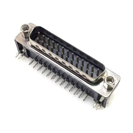
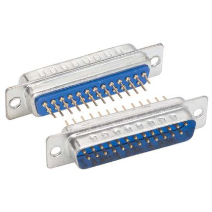
hese DB25 right angle connectors are designed to be mounted on printed circuit boards. All 25 pins and two mounting tabs (locking forks) extend through the circuit board, providing a convenient and sturdy connection.
These connectors are the 0.318″ set back style. This means that the distance between the connector face and the closer row of pins is 0.318″. See the drawing below.
Connector Setback
Connector Setback (Face to pins)
Setback = 0.318″
Connector Hardware, Clinch Nuts
Some connectors include what are called ‘clinch nuts’ as part of the hardware on each side of the connector. The clinch nut is essentially a threaded rivet that sandwiches together the PCB fork, the plastic connector body, and the front metal face plate. The hex ‘jack screws’ then thread into the clinch nuts.
On connectors that do NOT include clinch nuts, the hex jack screws only thread into the PCB forks. If the hex jack screws are removed, the PCB forks and the front metal face plate are then loose and can potentially fall off the connector until the jack screws are reinstalled. The main reason connectors are made this way is for cost savings when these aspects are not problematic.
On connectors with clinch nuts, the hex jack screws are still removable, but when removed, the face plate and PCB forks are still held secure by the clinch nuts. This can make the panel-mounting process easier, and also allows using hardware other than jack screws with the connectors (e.g. captive screws). The threading of the clinch nuts is also thicker than the PCB forks, which gives a stronger point for the jack screws to thread into.
Winford is discontinuing the NON-clinch nut style of connectors.


Reviews
There are no reviews yet.